LagEase
Benefits
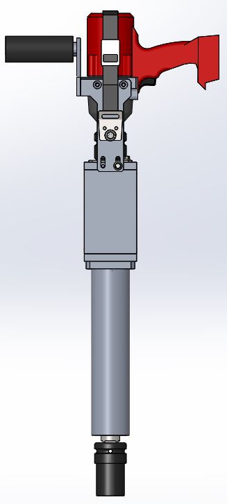
- Drives lags in 3 seconds
- Up to 20 pounds lighter than conventional hydraulic lag inserters
- No hazardous hydraulics, hoses, or fluids
- No gas-powered generators
- No setup time necessary
- Takes just one worker to operate
Goals
- Design a battery-powered lag inserter
- Minimize lag insertion times
- Minimize the cost and weight of the lag inserter
- Maximize the strength and useful life of the lag inserter
- Maximize the ergonomics of the lag inserter
Specifications
- About 30 pounds
- 3-second lag drives
- A rechargeable battery pack and commercially available drill
- Easy to transport anywhere the rail takes you
- No hydraulic system to risk leaks or environmental hazards
Drill Ease
Benefits
- 3-5 seconds per hole in wooden ties
- Only 30 pounds
- No hydraulics, hoses, or fluids
- No gas-powered generators
- No setup time
- One worker to operate
Goals
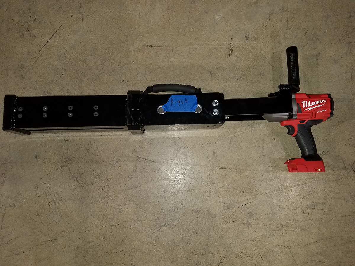
- Design a battery-powered tie drill
- Minimize drill time
- Minimize the cost of and weight of the drill
- Maximize the strength and useful life of the drill
- Maximize the ergonomics of the dill
- Implement safety features to cover the drill bit
- Provide an aligning feature to align the tool with the tie plate
- Develop a depth stop and spring assisted tool removal
Specifications
- About 30 pounds
- 3-5 seconds per hole
- A rechargeable battery pack and a commercially available drill
- Easy to transport anywhere the rail takes you
- No hydraulic system to risk leaks or environmental hazards
SpikeEase
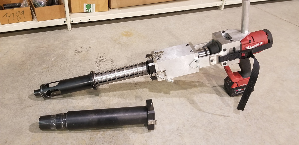
According to Focused Technology Solutions, the SpikeEase is the world’s most advanced battery-operated spike remover. Eliminating the need for hydraulic systems means un-tethering employees from service vehicles, heavy hoses, and expensive hydraulic power units.
Goals
- Design a battery-powered spike remover
- Improve maximum pull force
- Reduce the cost of and weight of the SpikeEase.
- Improve the ergonomics of using the SpikeEase in the field every day.
- Improve the strength and useful life of the SpikeEase
Specifications
- Weighs in at 30 pounds (not including drill or battery)
- 3-7 seconds per spike removal
- A rechargeable battery pack and a commercially available drill
- Easy to transport anywhere the rail takes you
- No hydraulic system to risk leaks and environmental hazards.
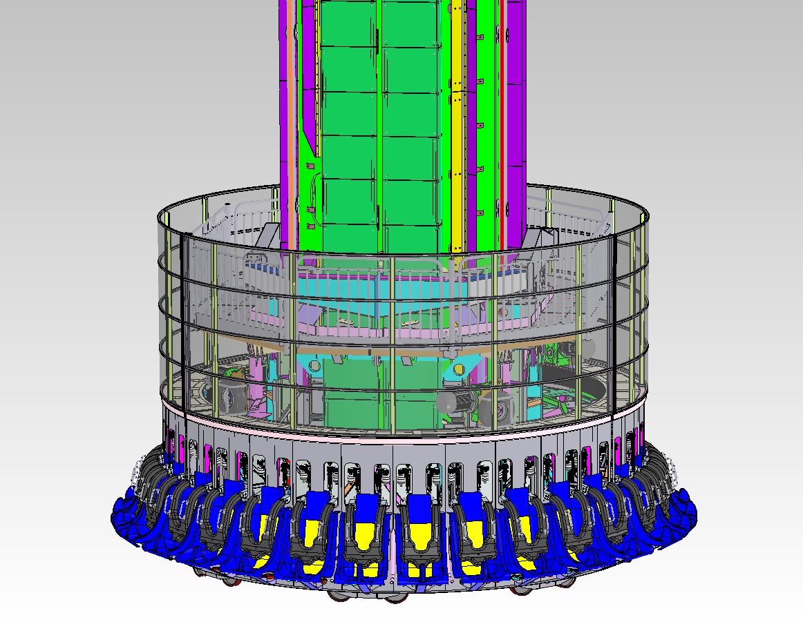
Finite Element Analysis of an Amusement Park Ride
For more information about our finite element analysis of this amusement park ride contact MJ Engineering or see below for details.
Project Description
MJ Engineering structurally reviewed this amusement park ride for Certification within the United States.
Capabilities Applied/Processes
Analysis
- Performed FEA Analysis of the Structure under dynamic & static loads.
- Analyzed ride under wind loads & seismic loads to demonstrate the structure conformed to the Local/State/Federal Regulations
Help to establish or guide the design of the following control systems
- Control Cycle
- Speed Control (braking)
- Safety Controls
- Operator Feedback
Provide Guidance and Analysis to the Customer During Installation
Confirm The Ride Conforms to Amusement Park Standards when Installed
Process Requirements
Specifications that were applied to various segments of the ride:
- ASTM F2291
- AISC 316
- AISC M015
- ANSI B11.TR3
- ANSI B77.1
- ASME B15.1
- ANSI/AWS D1.1, D14.4
- BS 5400-10
- SAE T833
- ASCE 7
More Info
Industry for Use
Amusement Park
Delivery Location
Virginia
Standards Met
ASTM
AISC
ANSI
ASME
AWS
BS
SAE
ASCE
Product Name
Finite Element Analysis of Amusement Park Ride
Machine Design of Custom Steel Pipe Handling System for the Manufacturing Industry
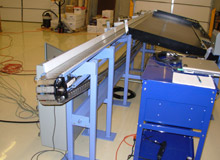
The custom designed machinery is capable of loading and unloading raw pipe lengths into a CNC threading and cutting cell. We created a handling system that is able to cingulate stock pipe from an accumulation hopper, convey pipe from the output side and sense pipe length and sort it into the correct bin on the discharge end.
To make the machine even more user-friendly, MJ Engineering designed a master PLC system that not only controls movement of the pipe into and out of the CNC cell but also has a touch screen HMI that allows easy operator access and troubleshooting.
We supported the client by offering full assembly and installation of both the steel pipe handling system and the PLC.
For more information on this design project please contact MJ Engineering or see below for details.
Project Description
MJ Engineering designed this machinery to load and unload a pipe into a CNC threading and cutting cell.
Capabilities Applied/Processes
Design/Engineering
- Design Machine in SolidWorks 3D CAD
- Design the Control System
Assembly
- Assemble the Handling System
- PLC Programming
- Electrical Enclosure Wiring
- Machine Wiring
Installation
- Install Handling System
- Final Assembly
- Final Wiring Connection
- Machine Leveling
- Securing Machine to Floor
- Installation Programming
Features/Benefits
Features
Loading equipment that was provided by MJ, which loads raw pipe lengths into the CNC cell. Individual pipes are cingulated onto rollers that convey pipe into the cutting cell.
MJ provided a master PLC system that controls movement of the pipe into and out of the CNC cell. This system has a touch screen HMI that allows easy operator access and troubleshooting.
The CNC cutting/threading machine can produce various lengths.
MJ provided a discharge / sortation conveying system that is capable of identifying individual pipe sections by length and delivering them to the correct bin.
Benefits
Manufacturer was Able to Reduce Manual Operation of the Cutting/Tapping Cell
More Info
Process Requirements
Ability to Cingulate Stock Pipe from An Accumulation Hopper
Feed Pipe into Cutting Cell Using Control Signals from PLC
Convey Pipe from the Output Side
Sense Pipe Length and Sort Into Correct Bin
Overall Cell Dimensions
Length: 42′
Width: 4′
Height: 5′
Material Used
Processes Steel Piping
Industry for Use
Pipe Manufacturing
Delivery Location
Ohio
Standards Met
Customer supplied specifications
Product Name
Design of Steel Pipe Handling System

